Introduction & Setup
In this tutorial, you'll learn how to use Castor by developing a Train Management System application. You'll start by defining your requirements, generate architectural diagrams and code, add new features, and see how Castor keeps everything synchronized.
Prerequisites
- Storage: 1.41 GB free space
- Memory: 4 GB minimum (8 GB recommended)
- Operating System: macOS 10.15+ or Windows 10/11
- Castor Account: Create an account if you don't have one
- Git: Installed on your machine
Before You Begin
- Download and install Castor
- Open the IDE and log in to your Castor account
Clone the Demo Project
We've prepared a Train Management System starter project. You can clone it using one of these methods.
Option 1: Clone from Terminal
git clone https://github.com/JustinSciortino/castor-train-management-system-demo.git
Then open the folder in Castor via File → Open Folder.
Option 2: Clone from within Castor
- Copy the repository URL:
https://github.com/JustinSciortino/castor-train-management-system-demo.git - Open Castor IDE
- Press
Ctrl+Shift+P/Cmd+Shift+Pto open the Command Palette - Type
Git: Cloneand select it - Paste the repository URL and press Enter
- Choose a folder to clone into and click Select as Repository Destination
- When prompted, click Open to open the cloned project
About the Demo Project: This is a NestJS application for a Train Management System. You'll use Castor to generate the design, diagrams, and code from three core requirements: Manage Trains, Create Schedule, and Book Ticket.
Configuring AI Options
Before generating requirements or design content, configure the AI Chat panel so the DAM agent behaves as expected.
Open AI Chat
- Click View -> AI Chat in the menu bar
- In the AI Chat panel, select
@DAM
Select a Language Model
To choose which model the DAM agent uses:
- Click the three-dot menu (⋮) in the AI Chat panel
- Go to Agent Settings -> DAM -> Language Model
- Select the model you want to use
Tip: You can change the model at any time from the same menu.
Understand Chat and Act
Use the toggle in the AI Chat panel to control agent behavior:
- Chat: The agent provides guidance and can propose file changes, but those changes require user approval before they are applied
- Act: The agent can directly create and update project files without requiring approval for each change
For this tutorial, use Act when you want DAM to write to requirements.md or design.md automatically.
Choose the Right Mode
Use the mode selector in AI Chat based on your goal:
- Requirements: Generate or refine requirements
- Design: Generate or refine
design.mdfrom the existing requirements
Important: Design mode updates
design.mdbut does not generate diagrams.
Exploring the Castor Panel
The Castor Panel shows all your project artifacts: requirements, design documents, and diagrams. Let's explore what's in the demo project.
Opening the Castor Panel
- Look at the Activity Bar on the left side of the IDE
- Click the Castor Beaver icon to open the Castor Panel
What You'll See
The Castor Panel displays your project artifacts in a tree structure:
- Requirements: The
requirements.mdfile which will contain our three requirements (Manage Trains, Create Schedule, Book Ticket) - Validation Schema: The
validation-schema.mdfile which defines validation rules for your requirements and design documents - Design: The
design.mdfile - Diagrams: All supported diagrams for your project
File Icon Colors: An orange icon indicates the file exists, while a grey icon means the file hasn't been generated yet.
Add the Requirements
In the Castor Panel, click Requirements to create requirements.md. Open the file and add the following three requirements:
### Use Case #1: Manage Trains

- **Actors**: Admin
- **Goal/Purpose**: Add and manage train records with trainNumber, name, capacity, and type.
- **Trigger**: Admin creates or updates a Train.
- **Preconditions**: None
- **Post-conditions**: Train record created/updated with unique trainNumber.
- **Priority**: High

### Use Case #2: Create Schedule

- **Actors**: Admin
- **Goal/Purpose**: Create a schedule linking a Train to a Route with departure/arrival times and seat inventory.
- **Trigger**: Admin creates a Schedule.
- **Preconditions**: Train and Route exist.
- **Post-conditions**: Schedule created referencing one Train and one Route.
- **Priority**: High

### Use Case #3: Book Ticket

- **Actors**: Passenger
- **Goal/Purpose**: Search available schedules, select one, book a ticket with payment and seat assignment.
- **Trigger**: Passenger books a ticket.
- **Preconditions**: Passenger and Schedule exist.
- **Post-conditions**: Ticket created with seat assignment; Payment confirmed.
- **Priority**: High
For future projects, you can write requirements in plain language and let the DAM agent structure them. In the AI Chat panel, set the dropdown to Requirements and prompt the agent to generate or refine your requirements.
Understanding the Validation Schema
Click on validation-schema.md to see how Castor enforces project standards. This file defines the required fields for each use case (like Actors, Goal, Priority) and ensures your design document follows a consistent structure. You can customize these rules to fit your project's specific needs.
Generate the Design Document
In the Castor Panel, click Design to create design.md.
For this demo, use the AI Chat panel:
- set the mode to Design
- ask the DAM agent to generate
design.mdfrom the existingrequirements.md
Castor uses your requirements as context to draft non-functional requirements and technical design details in design.md.
Important: Design generation does not create diagrams. Diagrams are generated in the next step when you analyze requirements.
Analyzing Requirements
Now that you have created requirements.md and design.md, the next step is to analyze your requirements so Castor can extract symbols, run sync, and generate initial diagrams.
Start Requirement Analysis
- In the Castor Panel, under Requirement Symbols, hover over Requirements
- Click the star icon beside Requirements to start analysis
When you click the icon, Castor begins extracting requirement symbols from requirements.md and analyzing your requirements.
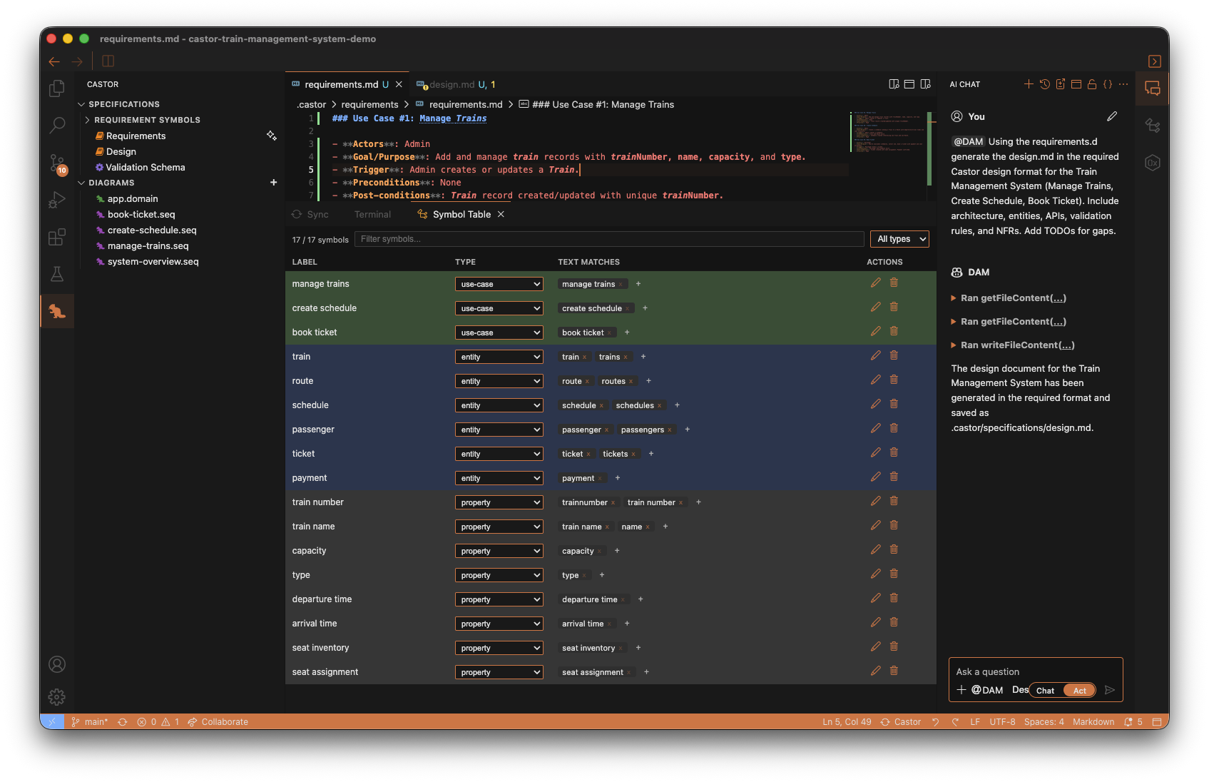
Inspect Extracted Symbols
After the analysis is completed, open the bottom panel and select the Symbol Table tab.
Here you can see the extracted requirement symbols (for example use cases and entities), along with their type and text matches. This is useful for validating that Castor interpreted your requirement language correctly.
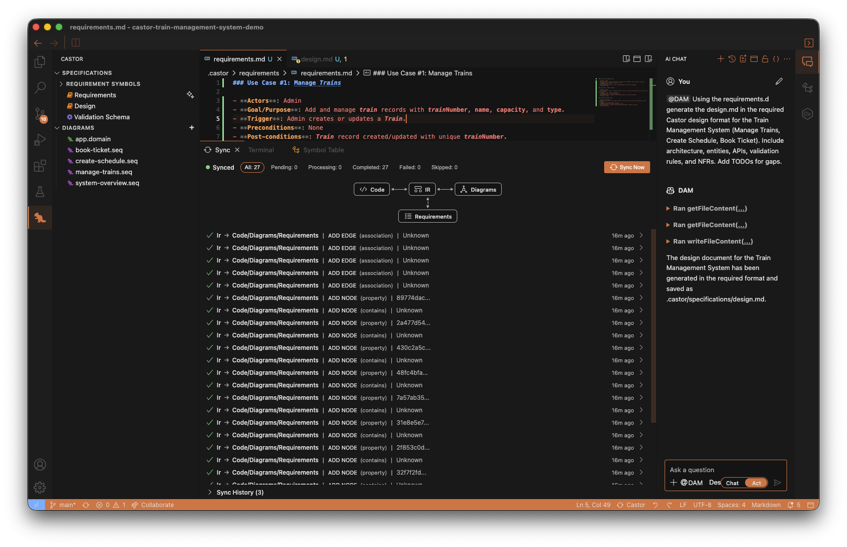
Track Castor Sync Activity
After symbol extraction is complete, Castor automatically triggers sync.
Open the Sync tab in the bottom panel to follow what happened during synchronization. You will see sync events such as nodes and relationships being added and connected across Requirements, Diagrams, and Code.
Review Generated Diagrams
Once sync finishes, Castor automatically generates:
- a single domain diagram, and
- sequence diagrams based on your analyzed requirements.
In the Castor Panel, expand Diagrams to review them.
Start with the domain diagram to validate core concepts and relationships, then open the sequence diagrams to inspect requirement flows. You can modify any generated diagram as needed.
Understanding Generated and Code-Generating Diagrams
After analyzing requirements, Castor can generate initial diagrams for you. Before creating code-generating diagrams, it helps to understand what each diagram type is used for.
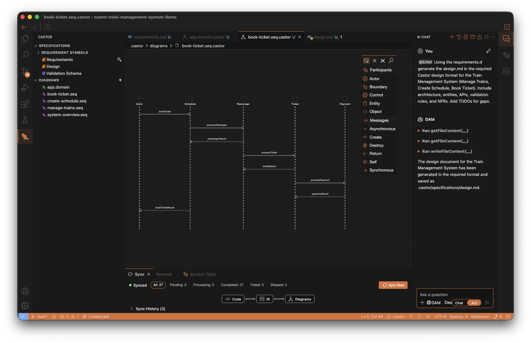
Open a Generated Diagram
- In the Castor Panel, expand the Diagrams section
- Open any generated diagram (for example, the domain diagram or a sequence diagram)
- The Diagram Editor opens so you can inspect and refine it
Diagram Editor Interface
Take note of the editor components:
- Canvas: The main area where your diagram is displayed
- Palette (right side): Contains elements you can drag onto the canvas
The Four Diagram Types
1. Domain Diagrams (.domain.castor)
- Generated from analyzed requirements
- Capture business concepts and relationships
- Do NOT generate code; used for requirements traceability
2. Sequence Diagrams (.seq.castor)
- Generated from analyzed requirements
- Capture interaction flows for use cases over time
- Influence and participate in downstream code generation context through sync/IR relationships
3. ERD Diagrams (.erd.castor)
- Entity-Relationship diagrams for data modeling
- Generate entity files (
*.entity.ts) - Define your data structures, properties, and relationships
- Sync bidirectionally with entity code files
4. Class Diagrams (.class.castor)
- Application architecture diagrams
- Generate services, controllers, and modules
- Produce
*.service.ts,*.controller.ts,*.module.tsfiles - Sync bidirectionally with application code files
Key Takeaway: Domain diagrams support requirements traceability. Sequence diagrams validate runtime behavior and participate in downstream codegen context. ERD and Class diagrams are the primary code-generating diagram types.
Promoting to Code-Generating Diagrams
Now that requirement analysis has generated your domain and sequence diagrams, you can use the DAM slash command to promote them into code-generating diagrams.
Run the /promote Command
- Open the AI Chat panel and select
@DAM - Make sure Act mode is enabled
- Run:
/promote
First-Time Project Config (If Prompted)
If .castor/castor.config.json does not exist yet, the DAM agent will ask you to create it and choose a framework:
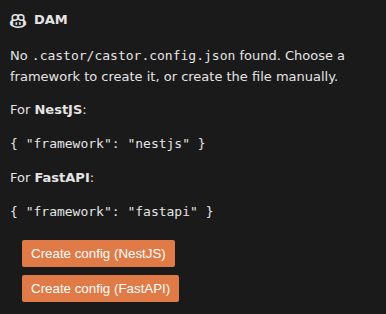
The DAM panel will display the config options and two buttons — Create config (NestJS) and Create config (FastAPI). For this tutorial, choose NestJS, then run /promote again.
What /promote Does
/promote uses your analyzed requirements artifacts (especially domain and sequence diagrams) to generate implementation-level diagrams:
- Promotes domain concepts into implementation concepts
- Creates or updates ERD and Class diagrams
- Triggers sync automatically, which then triggers code generation
You will inspect the generated code in the next step.
What You Should See
After /promote completes:
- New code-generating diagram files appear under Diagrams
- ERD diagram(s) are created
- Class diagram(s) are created for promoted features
- Sync/codegen activity appears automatically in the bottom panel
Tip: You can also promote specific concepts only, for example:
/promote Train Route
Viewing the Generated Code
After running /promote, Castor automatically syncs and generates code from your ERD and Class diagrams. In this step, you will inspect the generated files.
Finding the Generated Code
- Click the Explorer icon in the Activity Bar (file icon at the top left)
- Expand the
srcfolder - Open the generated feature folders and files
Explore the Code Files
Open different files to see how diagrams translate to code:
*.entity.ts: Generated from ERD diagrams (data entities, properties, and relationships)*.service.ts: Generated from Class diagrams (application business logic)*.controller.ts: Generated from Class diagrams (API endpoints)*.module.ts: Generated from Class diagrams (feature wiring and dependency registration)
Verify Diagram-to-Code Mapping
As you inspect files, compare them with your ERD and Class diagrams:
- ERD entities should match generated
*.entity.tsclasses - Class diagram services, controllers, and modules should match generated NestJS files
- Methods and relationships defined in diagrams should appear in code structure
For the Train Management demo, check files related to features such as train, schedule, and ticket.
Key Observation: The generated code mirrors your diagrams. This keeps design and implementation aligned and enables synchronization workflows throughout the project.
Updating and Editing Code-Generating Diagrams
In this step, you will edit code-generating diagrams and verify code updates after sync.
Update the ERD Diagram
- In the Castor Panel, open your
app.erd.castorERD diagram - Find the Passenger entity
- Add a new attribute:
name: string - Save the diagram (
Ctrl+S/Cmd+S) - Wait for sync to complete
- Open the generated Passenger entity file in
srcand confirm thenamefield was added
What This Confirms
- ERD edits update generated entity code
- Class diagram edits update generated services, controllers, and modules
- Sync/code generation runs automatically after save
Optional: Try More Diagram Edits (Add + Remove)
Now try your own add/remove changes in any ERD or Class diagram:
- Open any
.erd.castoror.class.castordiagram - Make one addition and/or removal
- Save the diagram
- Wait for sync to complete
- Open the related generated code file(s) and verify the changes
Reminder: Domain and Sequence diagrams guide analysis and design. ERD and Class diagrams are the primary code-generating diagrams.
Editing Diagrams Manually
You can make changes directly in the Diagram Editor. Here are the different edits you can make.
Diagram Edits You Can Make
- Add Elements: Drag classes, entities, or services from the Palette
- Create Connections: Use the Connection Tool to draw relationships
- Add Methods/Properties: Select an element and add via right-click context menu
- Delete Elements: Enable the deletion tool in the Palette and click on elements
Watch this walkthrough to see how to add entities, move them, create relations, and edit attributes and methods:
Remember — Only ERD, Class and Sequence Diagrams Generate Code: Changes to
.erd.castorfiles generate/update entity files. Changes to.class.castorfiles generate/update services, controllers, and modules. Changes to.seq.castorfiles participate in implementation/codegen context (for example, interaction-driven service/method structure). Changes to.domain.castorfiles do NOT generate code.
Remember to Save and Sync! After making diagram changes, save with Ctrl+S / Cmd+S, then click the Sync button in the bottom right of the IDE to synchronize your changes.
Synchronization in Action
This step focuses on Code -> Diagram synchronization. You will edit generated code and confirm that the ERD diagram updates automatically.
Try It: Code to Diagram (Passenger Entity Example)
- Open the generated Passenger entity file in
src - Add a new property, for example:
age: number
- Save the file (
Ctrl+S/Cmd+S) - Open your ERD diagram (for example,
app.erd.castor) - Locate Passenger and confirm the
ageattribute now appears in the diagram
Key Result: Synchronization is bidirectional. Changes made in generated ERD/Class code can flow back into diagrams, keeping both representations aligned.
Congratulations!
You've completed the Castor tutorial! You now know how to use all the core features of Castor IDE.
What You Learned
- How to open and explore projects in the Castor Panel
- How to configure AI options (model selection, Chat vs Act, Requirements vs Design mode)
- How to generate requirements and design documents with the DAM agent
- How requirement analysis extracts symbols, triggers sync, and generates a domain diagram plus sequence diagrams
- Understanding the four diagram types: Domain (
.domain.castor), Sequence (.seq.castor), ERD (.erd.castor), and Class (.class.castor) - How to use
/promoteto generate ERD/Class implementation diagrams and trigger code generation - Viewing and understanding diagrams in the Diagram Editor
- Exploring generated code and understanding how it maps to ERD/Class diagrams
- Updating and editing ERD/Class diagrams and verifying generated code updates
- How bidirectional synchronization keeps ERD/Class diagrams and code in sync (Diagram -> Code and Code -> Diagram)
Next Steps
Now that you understand the basics, try these next:
- Start a new project from scratch and create requirements with the DAM agent
- Create separate ERD and Class diagrams for different features
- Experiment with different diagram relationships (inheritance, composition, aggregation)
- Use domain diagrams to maintain traceability between requirements and implementation
- Explore the full documentation for advanced features
Need Help?
If you have questions or run into issues, we’re here to help:
- Contact us
- Join our Discord community
Build Fastor with Castor!